Hi every one,
You can now download “The Little story of the Underwater Cutting” in one single printable document at:
https://www.academia.edu/24883704/The_Little_Story_of_the_Underwater_Cutting
The second method of cutting under water to have emerged uses the principle of arc welding. Here again, this invention is due to the genius of a few great men.
The first is simply the English physicist Sir Humphry David (Edmund’s cousin) who in 1813 managed to create an electrical arc under water.
It will then be necessary to wait until 1890 to see appearing a first patent for a process of arc welding. The problem is that this first method uses bare electrodes without coating and therefore the arc is very unstable and the welds of mediocre qualities.
Fortunately ten years later the first coated electrodes are invented thereby bringing the first welding jobs. Very quickly during these works welders are going to realize that by increasing the current intensity it was then possible to cut or rather melt thin sheets.
Nevertheless, it will again be necessary to wait until the middle of the First World War to see someone use this process under water.
The first under water metal-arc cutting essays with a welding rod seem to have begun simultaneously in France, the United Kingdom and in the United States.
In France tests are performed under water in 1917 by the Soudure Autogène Française Company with two types of electrode: small diameters steel électrodes and large diameters carbon electrodes.
But the generators that are used in those days in France are not powerful enough and the tests are inconclusive. As a result on the French side the electrical cutting trials will not resume before 1924 (115).
The British Admiralty seems to have had more success with this process since the Deep Diving and Submarine Operations book from Siebe-Gorman mentions that its divers used it during World War I (116).
At the American side it is to the firm Merritt-Chapman & Scott that returns the merit to have developed this system that will also be used on the S.S St Paul in addition to the gas burning torch.
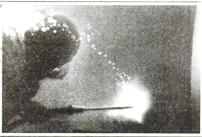
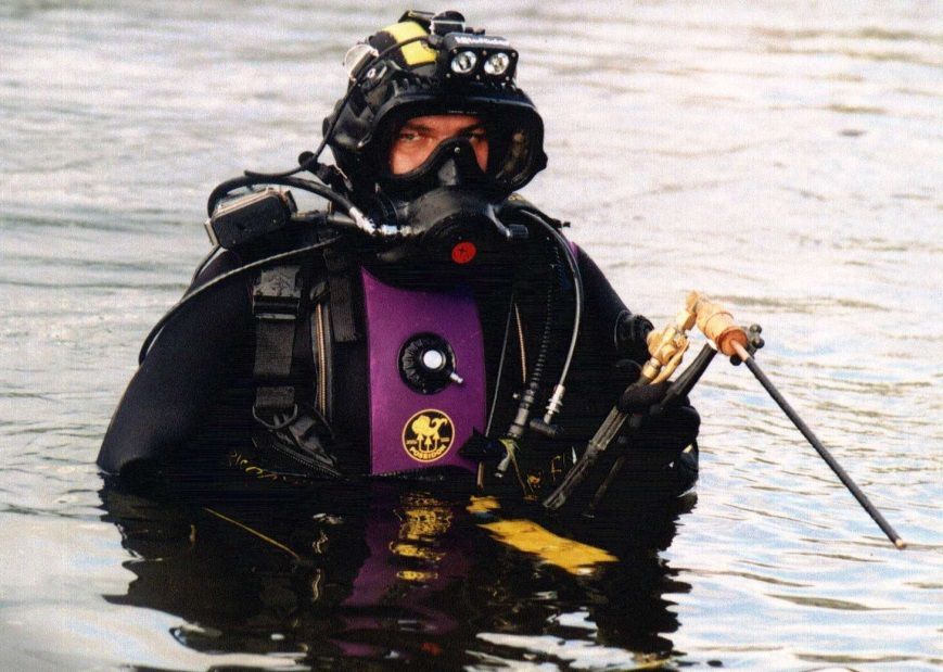
Photo n° 60: Diver with cutting torch (117)
From June 1918 R. E. Chapman and J. W. Kirk applies for a patent for a method of cutting under water by means of the intensity of an electric arc.
For that purpose, the inventors plan 3 manners to cut the steel.
1° by means of the only heat generated by the electric arc of a carbon electrode.
2° by means of a carbon electrode perforated by 3 holes allowing the passage of a flux of oxygen.
3° by means of a carbon electrode provided by two small pipes allowing the passage of a flux of oxygen.
Figure n°26: description of the process (118)

In practice we will later see that only the use of the hollow electrode will be favoured.
This patent will be followed a little later by another one also filed by Chapman concerning this time the electric cutting torch which is used by its divers.
Figure n°27: Sketch cutting torch (119)
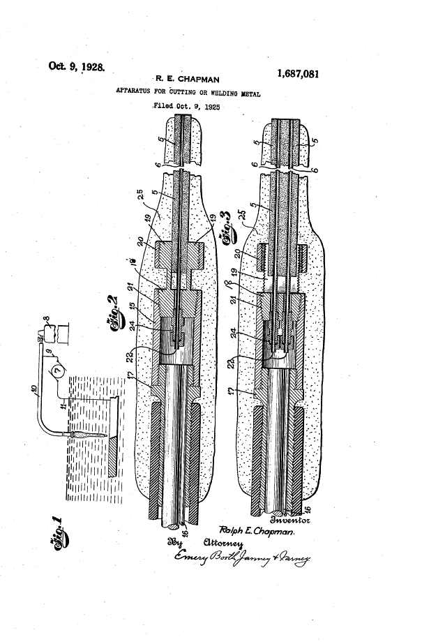
Photo n° 61: oxy-arc cutting torch (120)

To train its workers to this new technique a training tank is installed within the company and very quickly the divers will adopt this technique to make some difficult cuttings.
Photo n° 62: Merritt-Chapman & Scott cutting equipment and training tank (121)

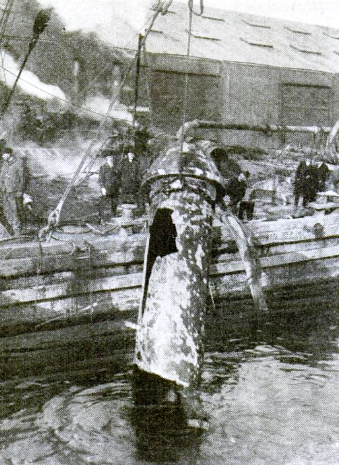
One of the first practical uses will be done in 1919 on the freighter Lord Dufferin. It collided with the steamer AQUITANIA and to prevent it from sinking the ship had been stranded on the island of the Statue of Liberty. About twenty meters from its stern had been partially ripped off and to allow its dry-docking, the divers had to cut by oxy-arc about 8 tons of wrinkled sheets.
Photo n° 63: Lord Dufferin in dry dock (122)

Another great performance realized by the guys of this company took place in New York in February 1922. At that time a dredge accidentally pierced a 36 inches drinking water pipeline feeding Stade Island one of the New York districts.
Photo n° 64: Cutting training (123)

The repair planned to remove the damaged section and replace it with a steel spool piece.
Several working days were necessary to clear the damaged part of the pipe which rested under a thick layer of mud and thus enable divers to start cutting. But the job is not simple because despite the mud removal some sections of the pipe must be cut from the inside which one can imagine was far from comfortable with a Mark V helmet on the head.
Furthermore, the main was made of thick (80 mm) cast iron which we know is not readily oxidized. Despite these difficulties the divers finally managed to complete this work within 9 days during which they plunged 24h / 24h and cut not less than 10 linear meters of pipe (124).
Photo n° 65: Removal of the damaged section (125)
And to end we can still mention the cutting realized by John Tooker in also some difficult conditions of around thirty piles that were protecting one of the Texas bridge piles on the Atchafalaya River, Melville which had been torn away and twisted by a big timber fender pier adrift.
Figure n° 28: Detail of sheet piling (126)

The work that began November 17, 1922 had required 114 hours of diving among which 67 hours were devoted exclusively to oxy-arc cutting (127).
Becoming aware of the capacities of this electrical cutting tool the US Navy will also develop a first oxy-arc cutting torch. Unlike the Chapman and Kirch torch which we recall is straight, the US Navy one is square and can work with an electrode pointing at 90 °. Among those who participated in the design and the trials we find in particular the Chief Petty Officer John Henry "Dick" Turpin, who was one of the first African American Navy divers.
Photo n° 66: The diver J. H. Turpin (128)

Thanks to this torch the Navy divers will be able in 1927 to intervene effectively in the refloating work of another submarine the S-4, in which no less than 564 dives of any kinds will be realized (129).
In France in 1924, the Société de la Soudure Autonome Française resumes under the direction of Mr. Lebrun the essays of oxy-electric cutting she had interrupted in 1917 and on June 10, a diver managed using a coated iron tube (4mm inside diameter and 8 mm outer diameter and 80 cm length) to cut a sheet steel section of 20 mm in thickness thanks to a series of contiguous holes (130).
The literature does not specify the type of coating, but it's a safe bet that it was adhesive tape because it (the coating) protected the cutters who worked barehanded from the effects of the alternating current (130). Given the success of the trials it was this technique which was going to be used a few days later to continue the cutting tests on the Tubantia which we remember had been interrupted following the explosion of the flexible hoses (see article 2).
This time a diver managed thanks to 6 iron electrodes to cut a length of 1.2 meters plate in one hour of time. The straightness of the cut had been assured thanks to the implementation of a wooden guide painted in white (130).
As shown, the electrodes used during the French trials were in iron and not in carbon but it is nevertheless this last type of prismatic electrode 30 cm long breakthrough by 2 holes for the arrival of oxygen that will continue to be used by European diving companies into the forties.
By 1932 another cutting method by means of electrode 8 to 10 mm in diameter (without oxygen) will be developed by Mr. Sarrazin but it will be very little applied because its implementation required an operating current of about 1000 amps (131).
In 1935 Siebe-Gorman also describes an oxy-arc torch in its manual. As we can see on the photo 67 it is also a linear shape.
Photo n° 67: Siebe-Gorman oxy-arc torch (132)

In 1939 the American Swafford applies for a patent for a new torch but it seems that this model was never marketed.
Figure n° 29: Sketch of the Swafford oxy-arc torch (133)

On the other hand, towards the same time the same Mr. Swafford also manufactures a cutting electrode composed of a brass tube of Ø 9,5 x 350 mm in which are either welded a small square electrode or 3 steel rods. In order to be properly insulated the electrode it is protected by 3-5 wraps of insulating tape.
This electrode that now contains 7 steel rods will be in service for a few years in the US Navy and will still be mentioned in the various Manuals until 1948.
Figure n° 30: Sketch of the Swafford electrode (134)

It will be necessary to wait until 1940 to see a real evolution in the design of electric cutting.
At that time the department of the United States Navy decided to adapt existing materials in the need for the time. The modernization of this equipment will be realized at the US Naval Engineering Experimental Station located in Annapolis, Maryland and the material will then be tested by the Experimental Diving Unit and Deep Sea Diving School in Washington as well as at the US Naval Training School located at Pier 88 in New York.
It is moreover this number of quay that will give its name to this new oxy-arc torch.
Photo n° 68: The Pier 88 cutting torch (135)

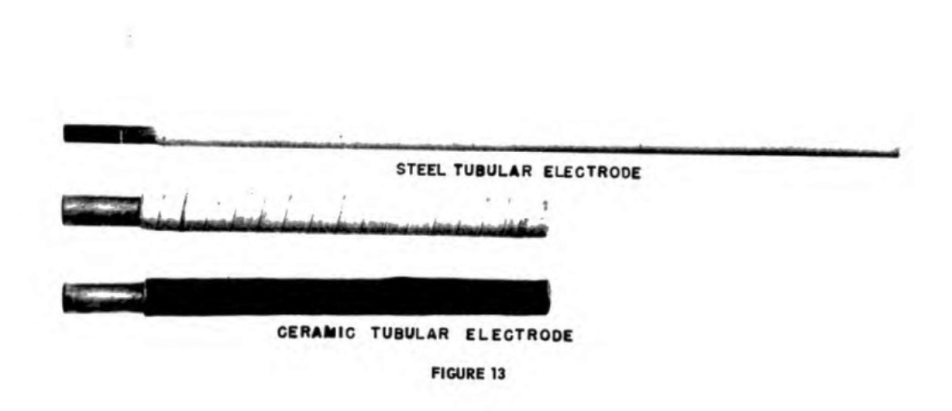
From that time also the big carbon electrodes are gradually going to disappear in favour of new finer tubular electrodes.
Two new types of hollow electrode will then be available: The ceramic electrodes and the steel tubular electrodes covered with a coating.
Photo n° 69: Models of electrode (136)
With this new equipment, the American divers are going to be able to work more effectively on the diverse ships which were sunk by Japanese aircraft. At Pearl Harbor, not less than 20,000 hours of diving will be needed to refloat most ships among which numerous hours were dedicated to cutting (137).
What is extremely surprising is that since the advent of electric cutting until the late forties a lot of cutting was also made with alternating current. In spite of the inconveniences and the risks of this type of electric supply the only additional precaution that were taken by the divers with regard to direct current consisted to better insulate the inside of the helmet by covering for example all metal parts which might to touched (139 ).
What is on the other hand to notice is that from the very beginning, it was recommended to turn off the electric current during cutting stops and changes of electrodes (see Chapman and all patent process).
In Europe also the oxy-arc cutting begins to get modernized after the Second World War. If England and to a lesser extent in Italy they continue to favour the use of carbon electrodes until the late sixties.
Photo n° 70: Siebe-Gorman cutting set (140)

Photo N° 71: Diver using an Italian torch (141)

In France, Belgium and possibly other countries we begin on the other hand to quickly use the steel tubular electrodes "Oxycuttend" manufactured by the company Arcos and the pink electrodes of Craftsweld. These two cutting rods were covered with a rutile coating which had the advantage to generate an extremely stable arc.
On the other hand this coating degraded rather quickly in the water and it was therefore better to protect the electrodes with insulating tape. To avoid this inconvenience Arcair launches on the market in 1971 the SEA-CUT.1, an electrode composed of a mixture of carbon and graphite which does not contain more than a simple plastic coating.
Photo n° 72: SOGETRAM diver doing some cutting training (142)

Each type of electrodes available had good cutting performance, but also some disadvantages. The big advantage of the carbon and the ceramic electrodes was their burning time which was generally 10 times higher than that of steel electrodes (143). They were also a little shorter what facilitated the work in confined spaces. On the other hand these electrodes broke very easily and the kerfs were rather narrow. Thereby they become less efficient than the plates became greater than 19 mm.
In the years that followed various oxy-arc cutting torches will be marketed everywhere (ARCOS, BECKMAN, CRAFTSWELD, ARCAIR, BROCO).
All are equal in quality if used and maintained properly.
Figure n° 31: Sketch of the Craftsweld torch (144)

Photo n° 73: Beckman cutting torch (145)

Photo n° 74: Russian cutting torch (146)
Between 1975 and 1978, basing probably on the principle of the thermal lance cutting (see below) as well as on what Swafford had invented in 1939, the Broco Company is developing the first ultra-thermic electrodes.
These are constituted by a fine steel tube 0.7 mm in thickness in which are crimped 7 metal wires of Ø 2.4 mm. Among these one is in a different alloy which allows the maintaining of an exothermic reaction after the cut of the electric current.
Photo n° 75: Electrodes Broco (147)

This electrode has a number of advantages compared with the steel tubular electrode such as that of requiring only a low intensity current (150 Amps) to work and thus a less heavy generator can be set up on construction sites.
Another undeniable advantage of this type of electrode is due to the fact that thanks to her exothermic reaction it can cut a larger number of materials that are oxidizing or not.
Its implementation is also easier because thanks to the fact that she can burn almost any material the cleaning of the surface to be cut needs no longer be as neat and finally learning how to use it is easier than that of cutting with steel tubular rods.
As a result, this type of ultra-thermic electrodes is fast going to dominate the market and its principle will rapidly be adopted or copied by other manufacturers or even private entrepreneurs who are going to produce in their turn this type of electrodes (Comex pro, Magnumusa, Divex, Arcair, HBS and many others).
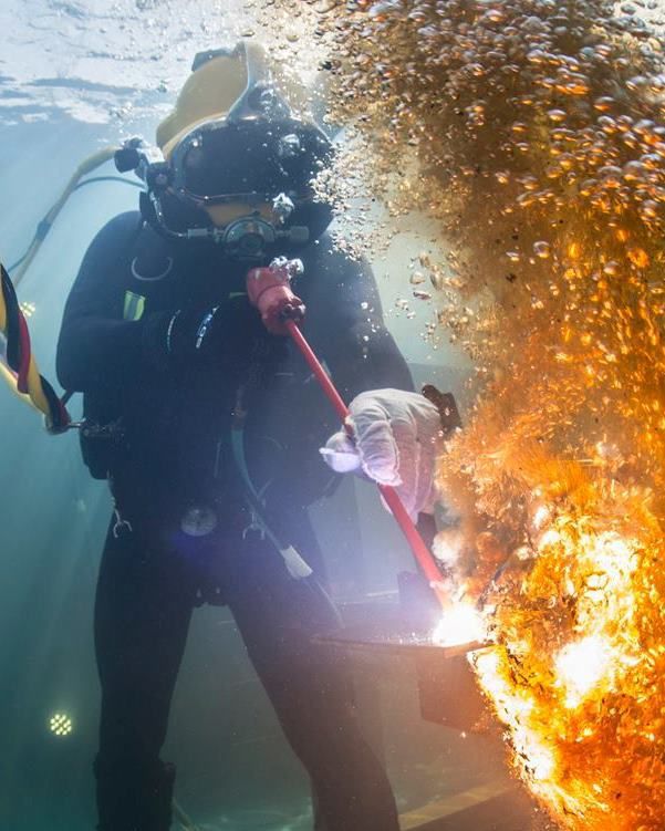
Photo n° 76: Cutting with an ultra-thermic electrode (148)
As mentioned a little earlier, the inventors of this new ultra-thermic electrode were probably inspired by another process of cutting: The thermal lance.
It consists of a steel tube of about 3 meters long with diameters ranging from 13 to 21 mm packed with alloy steel rods. It was invented in the 1930s by the French company Air Liquide, which was itself based on the invention of Ernst Menne German who in 1901 developed an oxygen lance for opening furnace taps in steel blast furnaces (149).
Thanks to its high combustion temperature thermal lance can pierce virtually any type of material. Regarding its use in water, it begins just after the Second World War where it is mainly implemented to create boreholes in the cement or the concrete that filled the holds of some wrecks.
By 1968 the American Marine discovers that this type of oxy-lance is used in Europe and thinks that the process could be used in some salvage operation and therefore asks the Battelle Memorial Institute to conduct an investigation on the risks incurred by the divers (150).
The result of the study was clear: process too dangerous to be used under water because of the high risks of explosion.
Despite these risks, certain diving company will nevertheless use the thermal lance in the end of the 70s for the opening of cavities in the reinforced concrete structures of some offshore platforms (151).
Currently, the thermal lance does not seem to be more used than by small companies not always aware of the risks or for the cutting of big piece when no other cutting mode is possible.
Picture n° 77: Cutting of a pipeline using a thermic lance (152)

It is then the turn of Reginald Clucas to arrive on the market with a new product.
Probably that this one has in the circle of acquaintances divers who told him about the underwater electric cutting and limitations bound to the electrode burning time. He imagines therefore a system that will allow divers to cut much longer without having to continually change rods and which is also less bulky than long thermal lances.
As a result, in 1968 he launches on the professional diving market a thermic cutting cable for whom he is going to borrow the first name of his daughter Kerie (153).
Photo n° 78: Kerie Cable reel (154)
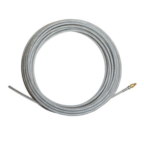
The operating principle of the Kerie cable is similar to the thermal lance but contrary to the metallic tubes containing alloy threats, the system consists of an outer sheath of plastic material in which a plurality of multistrand high carbon steel wires forming a hollow core to allow the passage of oxygen are set.
The ignition of the cable is done either by means of a torch flame or electrically with a current of 12 volts. The cables are supplied in lengths of 15 and 30 meters and in three dimensions 6, 9 and 12 mm
Figure n°32: Principle of implementation of the Kerie cable (155)

Photo N°: 79: Kerie Cable Set (156)

The burn rate is about 60 cm per minute what gives it a burning time of approximately 50 and 25 minutes by cable.
Although its principle of operation resembles that of the thermal lance, its melting temperature is however much lower (2700 °) what only makes possible that the cutting of ferrous metals.
One big problem with this cable (especially the first generation) was due to the fact that sometimes the plastic sheath was consumed faster than the metal core of the cable which was particularly annoying during cuttings without visibility and more than one diver did burn his hand.
Photo n° 80: Defect of functioning (157)

This is probably one of the reasons why this system has never really breakthrough and somewhat fell in oblivion for nearly 3 decades. Today, this problem appears to have been solved and the new system seems to be adopted by several navies and companies.
Photo n° 81: Diver using the Kerie cable (158)

In 2004 we see the arriving of the Swordfish rod from the Speciality Welds society (159).
This new electrode with a high content of iron oxide sold in diameter of 4 mm and 5 resumes the principle of the metal-arc cutting method (without supply of oxygen) used during the early electrical cuttings that is to say that the steel is not oxidized by an oxygen jet but is simply melted by the heat of an arc of about 400 amperes.
Photo N° 82: Result of a Swordfish cutting (160)

The latest thermal cutting method at disposition of the divers is that of the plasma arc.
Photo n° 83: Plasma arc torch and its control panel (161)

It was developed in the fifties but at that time it is not yet widely used because of some double arcing phenomena that damaged the electrode and cutting nozzle and it will be necessary to wait from then on until 1963 to see a real start in the surface cutting (162).
Fairly quickly the French company SOGETRAM discovers this process and decides to test it in the dive pool on Garenne sur Eure. The trials will however be quickly stopped because the vibrations and explosions generated by the tool during the cutting sequences were such that the staff feared the breaking of the portholes (163).
It will then be necessary to wait until 1985 to see the underwater arc plasma reappear in the former Soviet Union where this technique will be used together with the oxy-arc on the cutting job of the tanker Ludwig Svoboda that exploded in the port of Ventspils (164).
Photo n° 84: Wreck of the Ludwig Svoboda (165)

One of the problems of the implementation of the underwater arc plasma is bound to the fact that this process runs at 120-200 V arc voltage and has an open circuit voltage of 250-400 V what exceeds very widely the 30 volts recommended by most regulations (166).
Nevertheless from the beginning of this 21nth century the British company Air Plasma Ltd decides to adapt one of their systems for under water use and managed to eliminate electrical hazards for the divers. Their torch will be used the first time in March 2005 on a project of Mermaid Offshore Services in South Korea on which the divers will cut a series of holes of varied shapes and sizes in a steel sheet 32 mm located at the base of a platform (167).
The same torch will also be used in Canada in 2006 for the underwater cutting of 1500 m of sheet piles (168) and more recently in the United Kingdom to that of a curtain of about 800 m (169). Unfortunately no feedback is available concerning the possible difficulties met during the cutting of the locks and therefore it is a safe bet that only flat parts have been cut by the torch.
One of the advantages of the plasma arc is that the cutting generates relatively little debris and thus this cutting method is also used in nuclear power plants for the dismantling of some submerged structures. In most cases, the torch is remotely manipulated from the surface, but recently the divers of an American company specialized in this type of works cut out all the internal components from four steam generators (170).
Photo n° 85: Cutting trial with the underwater plasma torch (171)

But apart from these few particular applications there are very little echo’s concerning other types of underwater cutting work using this method.
Conclusions:
As we have seen through these five articles, as well as through the information of Figure n° 33 which represents the cutting speeds achieved during some tests performed in December 1940, the various tools were relatively productive and allowed to perform tasks that without them would have been impossible to make.
Figure n° 33: Length of cut made in 12 minutes using various cutting processes (172)

Today because of its ease of learning one favourites especially the cutting with ultra-thermic rods. Yet in the point of view of cutting speed per hour, if we except the plasma arc which is currently only used for specific applications and can cut the rate of 3 cm / sec (108 m / h) (173), the undisputed champion for most cutting operations in civil engineering still remains the underwater gas burning torch because used in good conditions and by some competent diver it can reach the speed of 66 m / h (174). It is followed rather far by the oxy-arc cutting (30,5 m / h) (175) and the ultra-thermic cutting (24,5 m / h) (176).
Referring to Figure 33, it is surprising to notice that the cutting speed mentioned for the oxy-hydrogen cutting is so low (7.5 m / h) as it does not correspond to the reality of the time when speeds were rather situated around 36 m / h (177).
It is therefore likely that this test was realized by a diver non-specialized in this type of cutting.
Figure n°34: Extrapolation Figure n° 33 to current performance (174 ,175, 176)

Despite the efficiency of these tools it is clear that both in civil engineering and offshore, thermal cutting operations have greatly diminished.
This is due to several reasons. On shore where these tools were primarily used for cutting of sheet piling it is partly due to the fact that first the steel prices increased sharply and secondly powerful hydraulic extracting tools were created during these last years which have therefore allowed the removal of the piles in their entirety.
In offshore, this mode of cutting also tends to be replaced by methods less risky for divers. Indeed, regardless of the method that is used it always generates a more or less large quantity of highly explosive gas which if they are confined in an enclosed area near the cutting area may explode violently under pulse of incandescent slag.
Photo n° 86: Diving helmet having suffered the effects of an UW explosion associated with cutting (178)

This risk is moreover very real because since the invention of the first underwater torch dozen of divers have unfortunately lost their lives by cutting (179).
The problem is that because of this decrease of cutting work the experience is lost and the new divers hardly have the opportunity to practice.
Even in the commercial diving schools this technique is often approached only in a succinct way by teachers who themselves do not always properly master this process. Yet an effort should be made in improving this teaching because even if less used it is almost certain that during still quite some years thermal cutting will remain a valuable tool for the diver.
References:
(115) L’emploi du chalumeau et de l’arc électrique dans les travaux sous-marins 1945 Académie de Marine par Maurice Lebrun page 22
(116) Deep Diving and Submarine Operation by Robert H.Davis /Siebe,Gorman & Company LTD CWMBRAN, GWENT 175 Anniversary edition / page 228
(117) Popular Mechanics Magazine Aug. 1934 page 164
(118) http://www.google.com/patents/US1324337
(119) RALPH E. CHAPMAN, OF MIAMI, FLORIDA. APPARATUS Fon. CUTTING on WELDING METAL. Application ñled October 9, 1925.` Serial No. 61,391.
(120) Popular Science Nov.1932 page 52
(121) Popular Mechanics Magazine May 1922 page 682
(122) Pacific Marine Review 1919 page 598
(123) Pacific Marine Review 1922 page 338
(124) Pacific Marine Review 1922 page 338
(125) Popular Mechanics Magazine May 1922 page 682
(126) Engineering news-record vol 90, n°10 march 8 1923 page 454
(127) Engineering news-record vol 90, n°10 march 8 1923 page 454
(128) http://paris-tx-naacp.blogspot.be/2011_08_01_archive.html
(129) Marine Salvage by Joseph N. Gores 1972 David & Charles page 119-123
(130) L’emploi du chalumeau et de l’arc électrique dans les travaux sous-marins 1945 Académie de Marine par Maurice Lebrun page 23-24
(131) L’emploi du chalumeau et de l’arc électrique dans les travaux sous-marins 1945 Académie de Marine par Maurice Lebrun page 30
(132) The Historical Diving Society Italia hds_48 pdf page 9
(133) http://www.google.com/patents/US2210640
(134) Divers Manual 1948 US Navy Training School (Salvage) Navy Yard Annex Bayonne New Jersey/Reproduction by the Historical Diving Society USA Santa Barbara, California fig.17
(135) Divers Manual 1948 US Navy Training School (Salvage) Navy Yard Annex Bayonne New Jersey/Reproduction by the Historical Diving Society USA Santa Barbara, California fig.10
(136) Underwater Work by Cayford Cornell Maritime Press 1966 page 93
(137) Marine Salvage by Joseph N. Gores 1972 David & Charles page 299-300
(138) L’emploi du chalumeau et de l’arc électrique dans les travaux sous-marins 1945 Académie de Marine par Maurice Lebrun page 30
(139) L’emploi du chalumeau et de l’arc électrique dans les travaux sous-marins 1945 Académie de Marine par Maurice Lebrun page 30
(140) Deep Diving and Submarine Operation by Robert H.Davis /Siebe,Gorman & Company LTD CWMBRAN, GWENT 175 Anniversary edition / page 228
(141) https://www.facebook.com/photo.php?fbid=10201906456641309&set=g.168828609978762&type=1&theater
(142) Brochure Sogetram
(143) Divers Manual 1948 US Navy Training School (Salvage) Navy Yard Annex Bayonne New Jersey/Reproduction by the Historical Diving Society USA Santa Barbara, California section 16
(144) https://www.google.com/patents/US2417650
(145) Commercial Oil-Field Diving by N.B. Zinkowski CMP 1971 page 170
(146) http://shelfspb.ru/upload/structure_1/1/1/6/structure_116/structure_property_image_83.jpg
(147) http://images.marinetechnologynews.com/images/maritime/w400/image-broco-underwater-22265.jpg
(148) https://www.facebook.com/kirby.morgan.apparel/photos/a.312480892127738.68021.288917144484113/1074685842573902/?type=3&theater
(149) http://www.saimm.co.za/Conferences/FurnaceTapping/203-Dienenthal.pdf
(150) Characteristics of Burning Bars Important to Their Being Used for Underwater Salvage Operations G.H. Alexander (Batelle Memorial Institute) Offshore Technology Conference 1969
(151) Anciens de Comex group memories of MCP 01 concrete cutting
(152) https://www.facebook.com/deivis.villalobos.9/videos/10207700185759910/
(153) http://www.google.ch/patents/US3591758
(154) https://www.ohgtech.com/wp-content/uploads/2014/12/IMG_5359-500x500.jpg
(155) U.S.Navy Salvage Manual Volume 1 Strandings, Harbor Clearance and Afloat Salvage Revision 2 2013 Published by Direction of Commander, Naval Sea Systems Command page 301
(156) NAVY EXPERIMENTAL DIVING UNIT REPORT NO. 7-84 EVALUATION OF THE KERIE CABLE THERMAL ARC CUTTING EQUIPMENT SUSAN J. TRUKKEN JULY 1984/ DEPARTMENT OF THE NAVY NAVY EXPERIMENTAL DIVING UNIT PANAMA CITY. FLORIDA 32407 page 9
(157) Experimental Diving Unit Report 24-72 / Evaluation of the Thermo-Jet cutting Torch by LTJ G B. LEBENSON, USNR and HTL.J.SCHLEGEL, USN/ Navy Experimental Diving Unit Washington Navy Yard 1973 page 11
(158) https://commons.wikimedia.org/wiki/File:Underwater_Kerie_cable.jpg
(159) http://www.specialwelds.com/products/swordfish.asp
(160) http://www.specialwelds.com/videos/swordfish-1.htm
(161) F.Hermans personal photo from plasma cutting test at BDC in Sept. 2012
(162) http://www.azom.com/article.aspx?ArticleID=1061#_Conventional_Plasma_Arc
(163) Information anciens de Sogetram (Pierre Graves et Felix Cobos)
(164) http://www.asptr.lv/en/performed-works.html
(165) http://www.asptr.lv/en/performed-works.html
(166) Code of Practice for The Safe Use of Electricity Under Water IMCA 045 page 22
(167) http://www.air-plasma.com/P30u.htm
(168) http://www.air-plasma.com/P30u.htm
(169) http://www.miles-water.com/underwater-plasma-cutting.html
(170) The Use of Divers for the Internal Underwater Segmentation of Steam Generators to Support Decommissioning - 14033 Charles A. Vallance (USA) Underwater Engineering Services, Inc.
(171) F.Hermans personal photo from plasma cutting test at BDC in Sept. 2012
(172) Divers Manual 1948 US Navy Training School (Salvage) Navy Yard Annex Bayonne New Jersey/Reproduction by the Historical Diving Society USA Santa Barbara, California section 17 Plate 2
(173) F.Hermans personal data from plasma cutting test at BDC in Sept. 2012
(174) F. Hermans log book 3 April 1980 Zeebrugge 16,5 m vertical cut in sheetpile in 15 minutes.
(175) F. Hermans log book 17 April 1981 G.O.M cutting of a 20” pipe in 3 minutes.
(176) F. Hermans log book 10 May 1991 Cameroun cutting of a 24” conductor pipe in 5 minutes.
(177) http://www.historicdiving.com/index.php/my-portfolio/videos/item/883-welding-under-water-video
(178) Evaluation Report of Swordfish Iron Oxide Cutting Electrode Shell April 2004 page 16
(179) http://www.thediversassociation.com/index.php/sheets incidents list and news paper achives